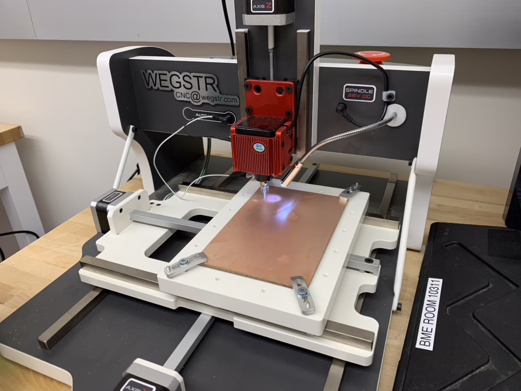
New Acrylic shield for the Wegstr CNC – PCB Mill
The department had this PCB mill that it purchased before I started that was seldom used. I picked it up, made a standard operating procedure (SOP) and have taught TAs and many students to use it as well.
The only problem is it has an exposed cutting tool and it’s so small and quiet, it’s hard to tell if it’s on. Also the boards are made of fiberglass, and while we use 3-in-1 or mineral oil to keep the dust down, it’s still quite a messy machine.
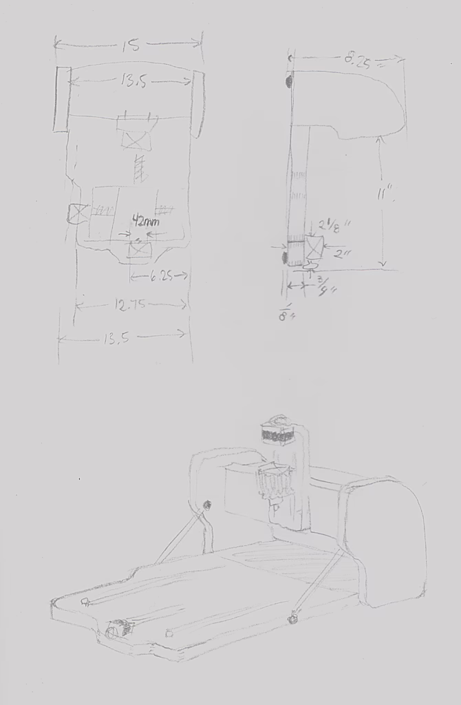
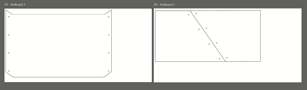
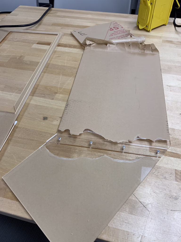
My first step is to get some measurements. In this case I put them straight into Adobe Illustrator. I added 1/8″ holes for sheet metal rivets.
So I went about building a shield. We only had 12x24in acrylic so I had to make due.
DCM solvent was added between the pieces and left to dry under ventilation over the weekend. I prefer 1/8in sheet metal rivets over clamping, to ensure nothing slides during the solvent bonding process. Clamps will leave footprints or marks in the DCM.
Plus, rivets look rad.
Here’s a good example of the bender used in action.
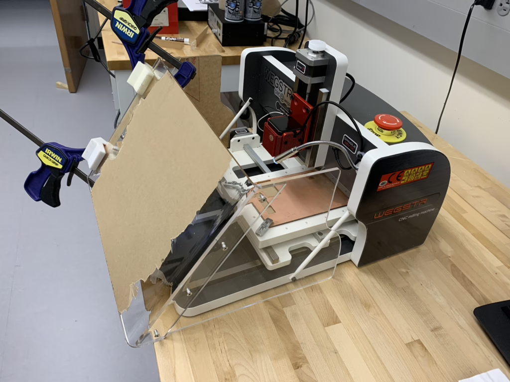
After the bender, acrylic stays hot for a very long time so we 3D-printed some clamp feet that will hold acrylic at different angles and radii while it cools. Here, you can see the 90deg clamps being used.
Here are similar corner clamps. https://www.thingiverse.com/thing:5819249
My tip for any acrylic process is to leave the paper on wherever possible. This prevents possible solvent fingerprints and unnecessary scratches.
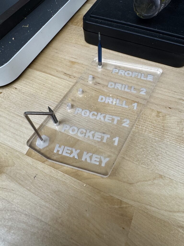
While I was on the laser cutter, I made a tool holder with the common order of Cut2D CAM cuts.
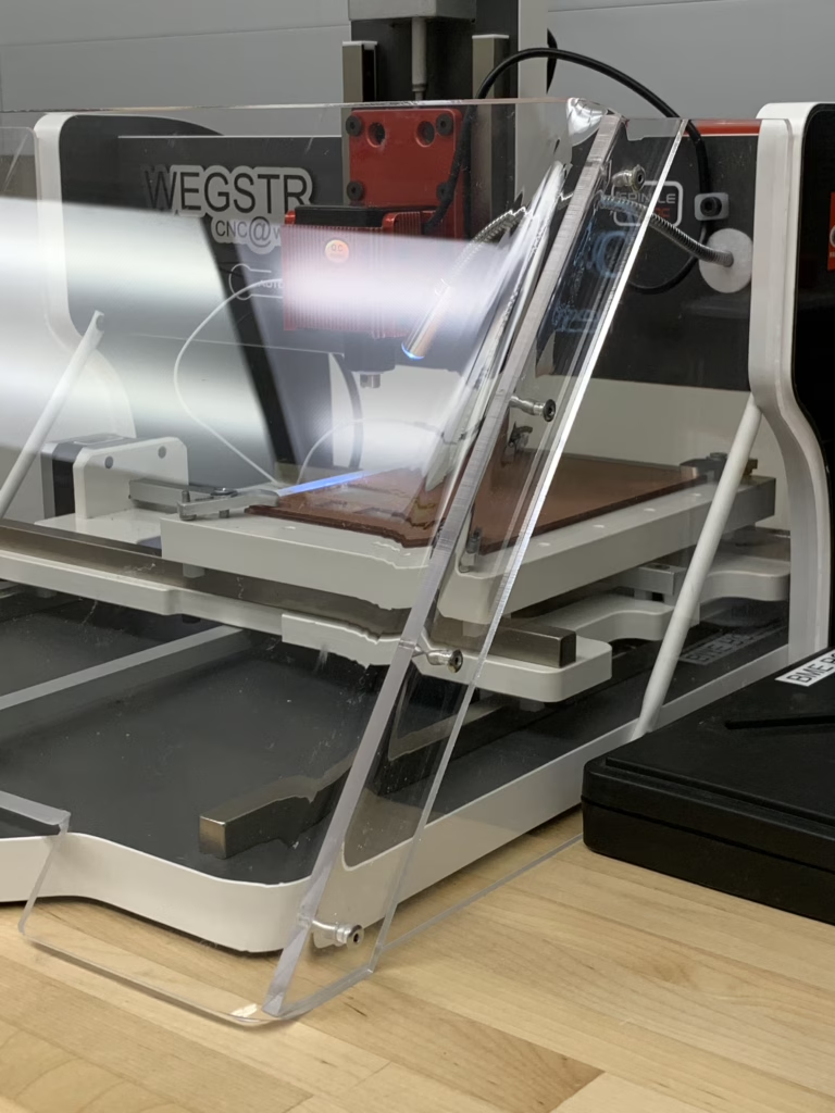
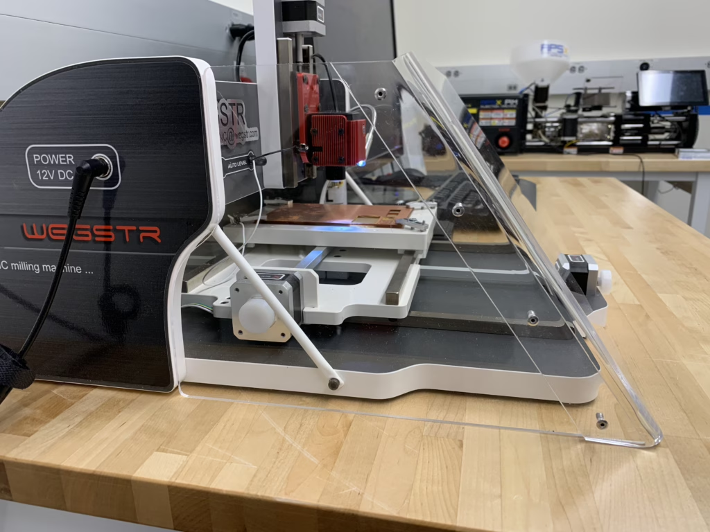
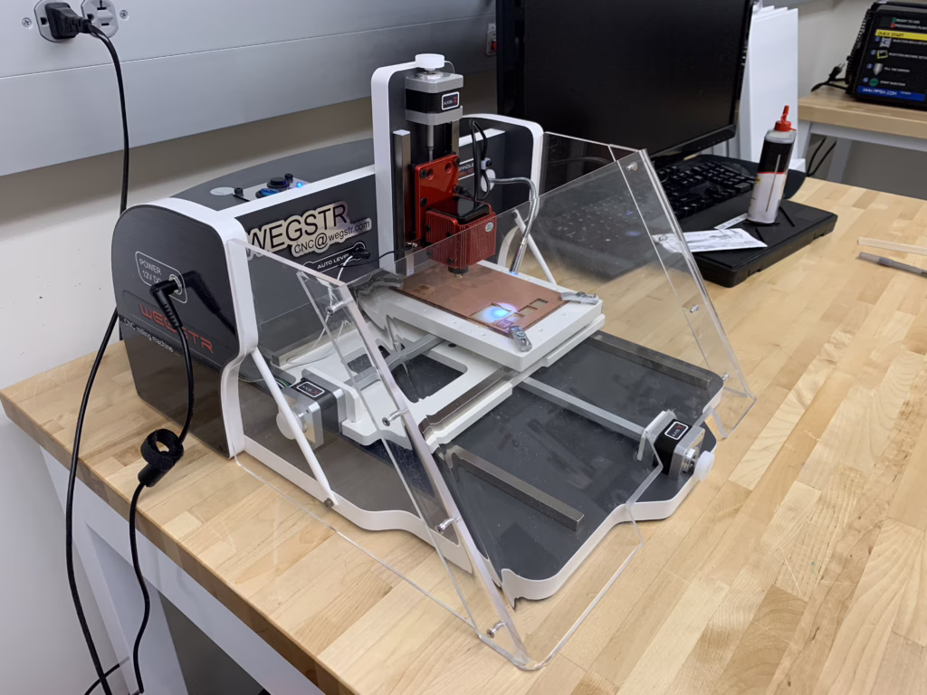
Glamor Shots.
Turned out great! We spray it down with windex once in a while.
You might notice there is a recess for the s-shape on the sides and front (y-axis) motor. This was done by hand with an expo marker and jeweler’s saw.
Quick PCB Process
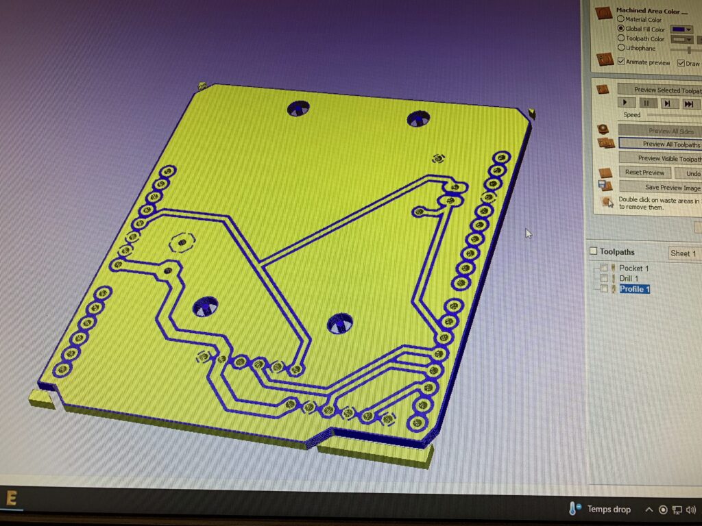
Our work flow starts in Tinkercad to replicate the breadboard 1-to-1, then to Fusion 360. From Fusion 360, a DXF is exported, then tools and toolpaths are chosen with Cut2D.
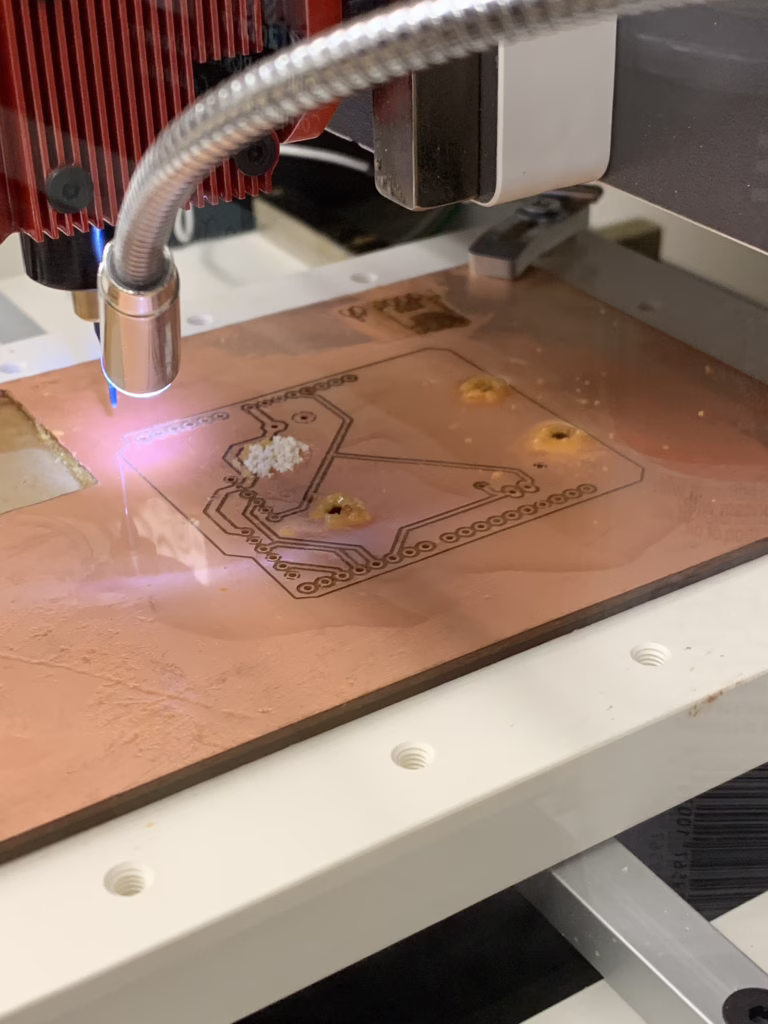
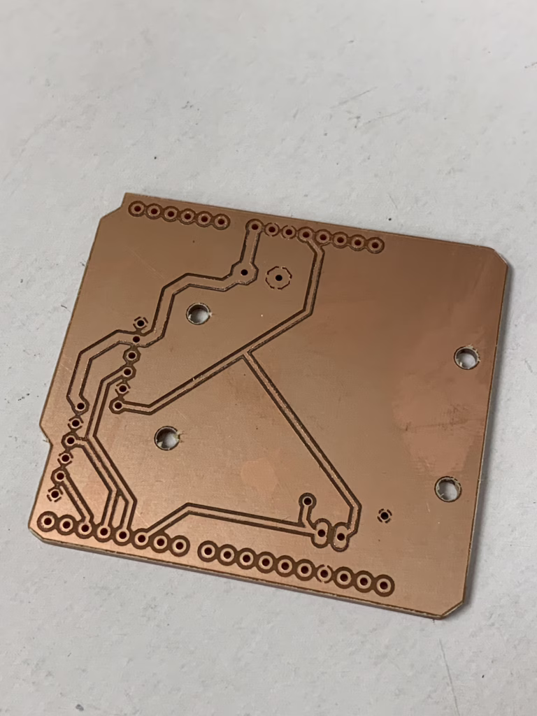
Here’s a finished bare copper board.
This will be inspected under microscope, sanded with 1500 grit, washed in acetone, then soldered at low temp (620°F) to prevent delamination. Finally, it will be sprayed with conformal coating to prevent oxidation.
I will post a more thorough PCB process later.
Thank you for reading!